The ITR Heat Oasis CH50 is a diesel hydronic heating system that is pre-installed in the 2019 Dutch Star. This provides for domestic hot water, and furnace heating for the whole RV and basement. The oasis is powered by either the diesel burner, or by electrical providing either 5k or 10k BTU. Engine waste heat is also used to provide heat energy to the distribution module, allowing for all system functions while driving without the use of additional heat sources.
All units are pre-wired for the engine loop pump. The panel will have to be replaced with one that provides the Engine Preheat Pump switch, and the pump will have to be installed inline.
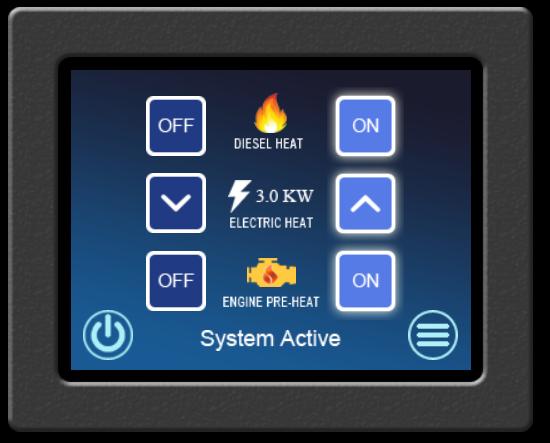
I opted to go with the ITRTouch Remote because I liked the look and it provided the function for preheat. When replacing an existing switch, you will need to order the over sized ITRTouch remote to cover the hole used by the original, which is taller and slightly more narrow than the new one. You can use the new ITRTouch without the pre-heat option. If you want to play with a demo of this switch, ITR has one on their website located here.
The new remote is 1/4″ wider than the standard switch. Once the hole is the proper size, the wiring harness will connect to this switch as a direct replacement. The pump was $295, and the new remote was $260.00 before any applicable discounts.
To perform the installation of the pump, you will need several items:
- 4 inches of 3/4″ ID heater hose
- Qty. 2 – 3/4″ hose clamps
- Qty. 2 – Hose pinch off pliers
- A dozen or so absorbent shop towels
- Qty 1 each – 16 gauge Fully insulated spade Connector Male/Female
When I started the install, I only had 2 sets of hose pinch pliers, and they were too bulky to properly close the hose in the cramped area. I ended up spilling about 2-3 cups of fluid before I gave up and reconnected the hose. I then researched what I could get delivered in 1 day from Amazon, and found these clamp pliers. What I liked about this style is that they are not vice-grip style, using a ratchet style system instead.

Newmar places the DM12 distribution panel behind a wall in the bay just behind the pass thru bay. Removing the wall will expose the DM12, and provide you with access to perform the full installation. Looking at the graphic for the DM12, you will see that the left side is where the engine coolant inlet and outlets are located. The pre-heat pump is installed on the outlet side, with the pump oriented to return the coolant to the engine.
Place 1 clamp on the inlet side, about 3 inches above the clamp, and another on the outlet side, about 6 inches from the clamp. I used a 3rd clamp and clamped the line higher up at the frame rails. This allowed me to capture the fluid in the line in a controlled manner, and have more flexibility with working with the hose.
Once the outlet is disconnected, place the pump in the final position and connect the engine side to the pump. There is not enough room to connect the pump and then re-position it to the back wall. The other hoses will not allow for the pump to fit through. Also pay close attention to the routing of the return hose, ensuring that it will not rub or kink. I had to alter how it routed from the frame rail down to get a proper alignment. I personally did not have the proper tools for easily handling the continuous pressure clamp, so I removed this and replaced with a worm-gear hose clamp.
Install the 4″ of 3/4″ heater hose to the outlet side of the DM12 and connect to the pump.
Secure the pump to the back wall, but use caution on the screws length,as the other side is where all of the 12v electrical connections are located.
The electrical needs to be connected to the pump using the spade connectors. The wires are red and black, and are exiting the DM12 above the outlet connector. They will be crimped together for protection. When doing the final routing of the electrical, make sure it does not rest along the heater.
After cleanup of any spilled fluids, place clean white towels around all connections that have been replaced, and run the engine for 30 seconds. Verify that your towels remain clean white, and that there is no leak.
Next, bring the ITR up to running temp and turn on the pre-heat option. Verify the pump is operating.
Since I had spilled so much fluid, I was worried about the air in the lines, and the loss of fluid. I ran the pre-heat pump for several hours, which was overkill, and then topped off the reservoir with coolant.
The final step was to take a test drive and bring the engine up to operational temps and let it remain for 30 minutes. This was about an hour total of driving. After that, I was satisfied that there would be no leaks, and closed it up.
For a view of the Remote Control operation of the Oasis, view this video.
For a view of the final pump installation and commentary, view this video.
